How to Disassembly Dell G15 5510 Laptop, Battery,keyboard and system board.
Removing the base cover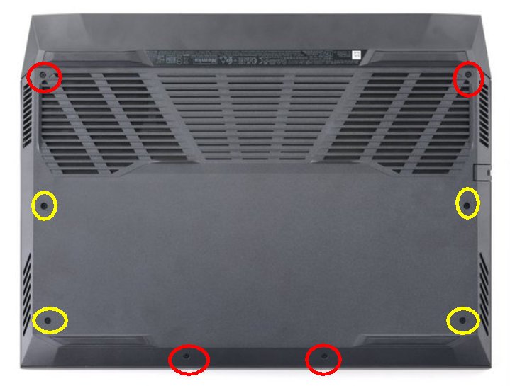
Steps 1. Loosen the four captive screws(YELLOW) that secure the base cover to the palm-rest and keyboard assembly.
2. Remove the four screws (M2x6)(red) that secure the base cover to the palm-rest and keyboard assembly.
3. Starting from the left corner, use a plastic scribe to pry the base cover and to release the base cover from the tabs. Lift the base cover off the palm-rest and keyboard assembly.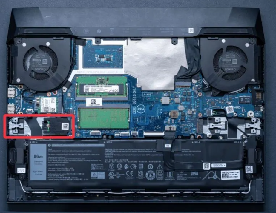
NOTE: The following steps are applicable only if you want to further remove any other component from your computer.
4. Using the pull tab, disconnect the battery cable from the system board.
5. Turn your computer over and press the power button for 15 seconds to drain the flea power.
Removing the solid-state drive in SSD slot one
Steps 1. Remove the two screws (M2x4) that secure the thermal shield to the solid-state drive and the system board. 2. Lift the thermal shield off the palm-rest and keyboard assembly. 3. Slide and lift the solid-state drive off the slot on the system board.
Removing the wireless card
Steps 1. Remove the screw (M2x4) that secures the wireless card to the USB board. 2. Lift the bracket that secures the wireless card to the system board. 3. Disconnect the antenna cables from the wireless card. 4. Slide and remove the wireless card from the wireless-card slot.
Removing the memory module
Steps 1. Use your fingertips to carefully spread apart the securing-clips on each end of the memory-module slot until the memory module pops-up.
2. Remove the memory module from the memory-module slot. NOTE: Repeat step 1 and step 2 to remove the other memory module, if installed on your computer.
Removing the battery
Steps 1. Disconnect the battery cable from the system board, if it is not previously disconnected.
2. Remove the four screws (M2x4) that secure the battery to the palm-rest and keyboard assembly. 3. Lift the battery off the palm-rest and keyboard assembly.
Removing the I/O board
Steps 1. Open the latch and disconnect the I/O board cable from the system board. 2. Remove the two screws (M2x4) that secure the I/O board to the palm-rest and keyboard assembly. 3. Remove the I/O board from the palm-rest and keyboard assembly.
Removing the speakers
NOTE: Note the position of the rubber grommets before lifting the speakers.
2. Peel the tape that adheres the speaker cable to the palm-rest and keyboard assembly.
NOTE: Note the routing of the speaker of cable and remove it from under the USB board before disconnecting the cable from the system board.
3. Disconnect the speaker cable from the system board and release the cable from below the USB board .
4. Lift the speakers, along with the cable, off the palm-rest and keyboard assembly.
Removing the rear cover
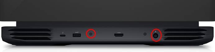
Steps 1. Remove the two screws (M2.5×5) that secure the rear cover to the palm-rest and keyboard assembly.
2. Remove the two screws (M2x2) that secure the rear cover to the system board.
3. Push the rear cover away from the system board and lift it off the palm-rest and keyboard assembly.
Display assembly
Removing the power-adapter port
Steps 1. Remove the two screw (M2x4) on the power-adapter port-bracket that secures the power-adapter port to the palm-rest and keyboard assembly.
2. Remove the power-adapter port-bracket from the power-adapter port.
3. Disconnect the power-adapter port-cable from the system board. 4. Lift the power-adapter port, along with its cable, off the palm-rest and keyboard assembly
Removing the system board
Steps 1. Remove the two (M2x4) screws that secures the Type-C bracket to the system board and lift the Type-C bracket off the system board.
2. Peel the tape that secures the display cable to the system board. 3. Open the latch and disconnect the display cable from the system board and place it on a flat and clean surface. 44 Removing and installing components 4. Open the latch and disconnect the power-adapter port cable from the system board. 5. Disconnect the fan cable from the system board. 6. Open the latch and disconnect the I/O-board cable from the system board. 7. Disconnect the speaker cable from the system board. 8. Open the latch and disconnect the keyboard cable from the system board. 9. Open the latch and disconnect the keyboard-backlight cable from the system board. 10. Open the latch and disconnect the touchpad cable from the system board. 11. Open the latch and disconnect the front LED light cable from the system board (optional). 12. Open the latch and disconnect the 4 zone keyboard cable from the system board (optional)
13. Disconnect the fan cable from the system board. 14. Open the latch and disconnect the power-button cable from the USB board. 15. Remove the (M2x4) screw that secures the USB board to the to the palm-rest and keyboard assembly. 16. Remove the (M2x4) screw that secures the left fan to the to the palm-rest and keyboard assembly. 17. Remove the four (M2x4) screws that secure the system board to the palm-rest and keyboard assembly. NOTE: USB board, and heat sink are attached to the system board. NOTE: After removing the screws, lift the system board from the top left and right sides of the heat sink. Ensure the connectors are released from the ports and pins on the left and right sides of your computer. NOTE: Place the system board on a clean and flat surface. 18. After performing all the above steps, lift the system board off the palm-rest and keyboard assembly along with the USB board, and heat sink.